Quest to disable LAN LEDs of an Intel NUC
Introduction
The Intel NUC D34010WYK has a LAN port with two integrated LEDs. Both are permanently on when a connection is established, with one LED blinking on network activity. This can be rather distracting, particularly at night. So I went on to figure out how to disable the LEDs. It's a general solution that should work with every OS, every NUC, and every somewhat recent Intel NIC (Network Interface Card). Perhaps most devices with an Intel Ethernet controller.
The most obvious and low-tech solution is to tape the LEDs. I haven't tried as an observation led me on a different path. I noticed that a few seconds into booting Ubuntu, the LEDs are briefly switched off. I concluded this must be done through software somehow. This didn't turn out to be entirely correct or useful, as the driver (kernel module) merely resets the controller when it loads, but made me curious enough to proceed.
First, a step back to know the controller used in the NUC.
$ lspci | grep Ethernet 00:19.0 Ethernet controller: Intel Corporation Ethernet Connection I218-V (rev 04)
Intel ARK has more information, including a very detailed 262-pages datasheet, which will prove essential.
Kernel
I wondered if the option to disable LEDs is perhaps provided through a kernel module parameter. I already knew the module name for recent Intel Ethernet devices: e1000e. If I hadn't, searching the Intel Download Center for I218 and filtering for Linux tells the same. And sure enough, the module is loaded.
$ lsmod | grep e1000e e1000e 226396 0 ptp 19395 1 e1000e
Many parameters, but none to change the behavior of LEDs. As confirmed by the documentation.
$ modinfo -p e1000e debug:Debug level (0=none,...,16=all) (int) copybreak:Maximum size of packet that is copied to a new buffer on receive (uint) TxIntDelay:Transmit Interrupt Delay (array of int) TxAbsIntDelay:Transmit Absolute Interrupt Delay (array of int) RxIntDelay:Receive Interrupt Delay (array of int) RxAbsIntDelay:Receive Absolute Interrupt Delay (array of int) InterruptThrottleRate:Interrupt Throttling Rate (array of int) IntMode:Interrupt Mode (array of int) SmartPowerDownEnable:Enable PHY smart power down (array of int) KumeranLockLoss:Enable Kumeran lock loss workaround (array of int) WriteProtectNVM:Write-protect NVM [WARNING: disabling this can lead to corrupted NVM] (array of int) CrcStripping:Enable CRC Stripping, disable if your BMC needs the CRC (array of int)
It turns out such a parameter was requested years ago, but denied by Intel with the following explanation.
I'm sorry, but this feature request was evaluated and denied because the majority of our customers require the LEDs to function as-is, and module parameters of this type are unacceptable.
So I downloaded the kernel model source, hoping to modify it, and eventually noticed a promising function.
/** * e1000_led_off_pchlan - Turn LEDs off * @hw: pointer to the HW structure * * Turn off the LEDs. **/ static s32 e1000_led_off_pchlan(struct e1000_hw *hw) { u16 data = (u16)hw->mac.ledctl_mode1; u32 i, led; /* If no link, then turn LED off by clearing the invert bit * for each LED that's mode is "link_up" in ledctl_mode1. */ if (!(er32(STATUS) & E1000_STATUS_LU)) { for (i = 0; i < 3; i++) { led = (data >> (i * 5)) & E1000_PHY_LED0_MASK; if ((led & E1000_PHY_LED0_MODE_MASK) != E1000_LEDCTL_MODE_LINK_UP) continue; if (led & E1000_PHY_LED0_IVRT) data &= ~(E1000_PHY_LED0_IVRT << (i * 5)); else data |= (E1000_PHY_LED0_IVRT << (i * 5)); } } return e1e_wphy(hw, HV_LED_CONFIG, data); }
Perhaps more complex than you'd expect such a simple task to be. Many constants and bit operations. Lots more in related functions. I figured this must be documented, presumably in the datasheet. Browsing it cut my plans to modify the kernel module short, as it spells out a better alternative: NVM (Non-Volatile Memory).
The PHY has three LED outputs that can be configured via the NVM. The default values for the PHY (based on the LED NVM word 0x18 of the LAN region) are listed in the table below.

If you're wondering why the table mentions 3 LEDs when the LAN port only has 2: the second LED is bi-colored and can switch state to either green (LED2) or amber (LED1).
As a closing note on the kernel module: the code does not do what it appears to. Its only purpose is to provide an interface for blinking a single LED on request, in order to identify a NIC or LAN port. It's unrelated to LEDs blinking on network activity or otherwise, which is done in hardware.
NVM
Writeable flash memory, which holds configuration, like the MAC address or power management settings, detailed in the table below. The LED configuration is stored in the previously mentioned word 0x18.

A minor detour first to explain the term word. It refers to a 2-byte (16-bit) value in little-endian order, meaning in reverse byte order. So value 0x1c10 is written 0x101c to NVM. Very simple to do manually, by just swapping bytes, but can be done programmatically too. (These will be useful later.)
# Python def swap(value): return hex(value >> 8 | (value & 0xFF) << 8) >>> swap(0x1c10) '0x101c'
// JavaScript function swap(value) { return '0x' + ((value >> 8 | (value & 0xFF) << 8)).toString(16); }; > swap(0x1c10) "0x101c"
Word 0x18 is encoded as follows.

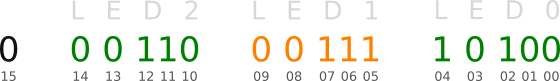
It's a bit sequence with 5 bits each per LED. The first 3 bits on each LED set the mode, detailed in the second table. The remaining 2 bits invert and blink the LED. Below is a visual explanation on how to read this, using the default values.
Such a sequence can be used directly with the swap function defined earlier, with 0b prefix to indicate bits.
> swap(0b0001100011110100) "0xf418"
Now to construct a bit sequence to turn LEDs off permanently. As you notice, there is no mode to just flat disable an LED. It's still possible to get effectively the same result. There are two solutions.
1Set the mode of each LED to 010, so LEDs are on on any connection, and set the invert bit on each LED. Ergo, LEDs are off on any connection. With a minor side effect: in case of no connection, LEDs are on. (When the network cable is pulled, or when the opposite side is off.)

> swap(0b0010100101001010) "0x4a29"
2Set the mode of each LED to 101, so LEDs are on only on a 10Mbps connection. Ergo, LEDs are off for either a 100Mbps or 1Gbps connection. Without side effect, as LEDs stay off in case of no connection.

> swap(0b0001010010100101) "0xa514"
There are two additional variants to the second solution, which exclude the other link speed combinations each. I'll leave constructing the bit sequence for both as an exercise to the reader. Of both solutions I prefer the second due to lack of side effect when a link speed can be excluded. Usually either 10Mbps or 1Gbps definitely can be. A way to get the negotiated link speed is to use dmesg.
$ dmesg -t | grep e1000e ... e1000e: eth0 NIC Link is Up 100 Mbps Full Duplex, Flow Control: Rx/Tx
So 0xa514 it is. Ready to write to NVM. The datasheet tells how.
Intel has an MS-DOS* software utility called EEupdate that is used to program the SPI Flash images in development or production line environments. A copy of this program can be obtained through your Intel Field Service representative.
That's no good. EEupdate is not publicly available. A bit of research reveals another Intel tool named LANConf, available for DOS, Linux, and Windows, which can also write to NVM, but can only be obtained by applying for a privileged account and signing a Non-Disclosure Agreement. Fortunately, ethtool can handle NVM too.
To read from NVM, use as follows. (EEPROM and NVM are used interchangeably from here on.)
% ethtool -e|--eeprom-dump devname [raw on|off] [offset N] [length N]
As per the NVM Address Map, word 0x18 is at NVM byte offset 0x30.
$ sudo ethtool -e eth0 offset 0x30 length 2 Offset Values ------ ------ 0x0030: f4 18
It matches the default value constructed earlier. Now to the important part: writing to NVM.
% ethtool -E|--change-eeprom devname [magic N] [offset N] [length N] [value N]
So offset, length, and value are obvious, but what does magic refer to? The manual knows.
Because of the persistent nature of writing to the EEPROM, a device-specific magic key must be specified to prevent the accidental writing to the EEPROM.
Where the device-specific magic key can be obtained from isn't documented anywhere. It appears to be kept somewhat secret on purpose. Only the file ethtool.c in the kernel module source code explains it.
eeprom->magic = adapter->pdev->vendor | (adapter->pdev->device << 16);
Here vendor and device refer to PCI IDs. There are numerous ways to get them, with the easiest perhaps being lspci.
$ lspci -nnq | grep Ethernet 00:19.0 Ethernet controller [0200]: Intel Corporation Ethernet Connection I218-V [8086:1559] (rev 04)
The bold numbers are the vendor and device ID respectively, in hex. So this should give the magic key.
// JavaScript > '0x' + (0x8086 | (0x1559 << 16)).toString(16) "0x15598086"
Very simple. Alright, commence writing.
$ sudo ethtool -E eth0 magic 0x15598086 offset 0x30 length 2 value 0xa514 ethtool: bad command line argument(s)
The value of value can only be a single byte. The length parameter repeats that byte. (This isn't documented.) Both bytes must hence be written separately.
$ sudo ethtool -E eth0 magic 0x15598086 offset 0x30 value 0xa5 Cannot set EEPROM data: Invalid argument
This rather non-descriptive error took me quite a while to figure out. The e1000e kernel module included with the default kernel of Ubuntu 14.04.2 does not support writing to NVM, in this case at least. Intel has instructions for compiling and installing the latest kernel module from source. Now it should work.
$ sudo ethtool -E eth0 magic 0x15598086 offset 0x30 value 0xa5 $ sudo ethtool -E eth0 magic 0x15598086 offset 0x31 value 0x14
And it does. Note: the LEDs remain unchanged until either the NUC is reset or the kernel module is reloaded.
Windows / Mac
I have not verified, but modifying NVM should also work for other OSes, unless the driver of that OS forces its own static LED configuration for some reason, which is unlikely. The driver can do that because the value from NVM is propagated to a PHY register after reset, which in turn is actually in control of LED configuration.
Several words of the NVM are accessed automatically by the device after reset to provide pre-boot configuration data before it is accessed by host software.
So the driver can write a value to the PHY register different than the default value said register initially gets from NVM. (This is what the last line in the source code function posted earlier does, and how the kernel module implements the identification feature.)